 |
 |
|
|
 |
 |
Enter Your E-Mail to receive
our Free monthly newsletter.
|
|
|

|
|
|
|
|
 |
|
|
|
|
|
 |
Procedures Establishing Quality Control in Field Installation
- Contractor shall install the specified anchor bolt assembly in C.I.P. or masonry foundation walls
|
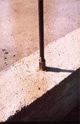
| Figure 6 |
at the specified points indicated on the engineered shop drawing plan, along with necessary reinforcing as indicated in the appropriate details. Minimum size anchor bolt shall be 7/16 by 12 by 3 except where special conditions, and where specified, an alternate and approved anchor may be used. The anchor shall be placed so that the coupler is embedded one half its length. The anchor is usually placed at the center of the cell. (See figure 5)
- B. Contractor, removing the plastic plugs from the couplers, installs the tension rods making sure that the rods are engaged into the coupler a minimum of ½ inch. In most cases the rod is a single section rod extending the full height of the wall. However, there may be certain conditions that would require the rods to be in multiple sections as in the case of tall walls. Contact an Integra® System Technical Representative for available options. Block are laid using type S mortar and applied to ensure fully mortared head and bed joints. Bee holes in the mortar joints should be avoided, which is extremely important when colored or architectural faced units are used. (Note: Polyurethane will stain the units and is not easily removed, if at all.) Conventionally grouted cells may at times be required. These will be indicated on the engineered drawings. In such cases, mortar may be used, though in lifts not greater than 8 inches. Care shall be taken that cell is fully grouted and properly consolidated as specified in the code. The plate bearing block is placed in the last course at each of the post-tensioned rods. In the case of tall walls, a tension block will be required at mid-height of the wall to act as a bar restraint. See Detail 15 under Wall Sections. When the masonry has been completed to the point necessary, the post-tensioning crew must be scheduled immediately. (In case of large projects or tall walls, consult with the Technical Representative for appropriate scheduling.) It is the contractors responsibility to ensure
the walls are properly braced until the walls have been tensioned and supported by the roof or floor structure.
The walls are tensioned using the specified steel plate washer along with the specified Direct Tension Indicator (DTI) washer. The DTI washer is placed between two hardened flat washers with the nibs of the DTI washer facing up. The 1/2 inch steel nut is then tightened until the bumps in the DTI washer are compressed
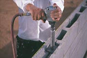 |
| Figure 7 |
causing the silicone to be squirted out and become a visible indicator of the correct bolt tension. (See Figure 6) The tensioning may be accomplished by mechanical means (Figure 7) or manually. If for any reason the tension assembly is loosened or removed, a new DTI washer MUST be used. (Note: Rods above openings are not tensioned, except under special conditions or as noted on the engineered plans.) Any detectable problems, such as missing tension rods and / or bolts will be reported immediately to the project superintendent. If remedial steps are required; consult a Technical Representative for proper procedures. Once the post-tensioning has been completed and all problems resolved, the appropriate certification shall be provided. Note: Special Inspection is only required on commercial projects or on any project where the masonry is more than one story. No special
inspection is required on residential, single-story unless specifically noted on the Engineered plans.
Example of Bolt and Rod layout
Figure 8
|
|
|
|
|
|
|
 |
|
|
|
|
|
|